Menu
Menu:

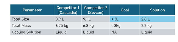
Overall Team Goal: create a smaller, lighter and more efficient traction inverter (motor controller for EVs) than industry.
-
Completed for fourth year design project
-
Team of four:
-
Me: mech for HV thermal components (design, analysis, manufacturing, validation)
-
1 software
-
1 electrical + controls
-
1 mechanical for exterior + mounting
-
-
Timeline: September 2023 – March 2024
Results

Assembly Level Design
Thermal Requirements
-
18 MOSFETs generating around 200W heat


Thermal Solution Overview
Thermal Design Summary
Why Liquid Cooling?
-
Air cooling assy was too large – the team decided that the size was the most impressive part of the inverter
-
Decided using heat sink specs:
-
1 large heat sink: 𝑅_𝑡ℎ = ∆𝑇/𝑄 = ((60−25)℃)/200𝑊
-
18 small heat sinks: 𝑅_𝑡ℎ = ∆𝑇/𝑄 = ((60−25)℃)/11.11𝑊
-


Cold Plate Overview
Material Selection
Coolant
-
Water:
-
Low viscosity
-
Good thermal properties
-
Cold plate
-
Al 6061:
-
Will not corrode
-
Good thermal properties
-
Fasteners
-
Zinc plated steel:
-
Will not corrode
-
Gasket
-
Silicone rubber, 60A hardness:
-
High melting point and low freezing point
-
Fittings
-
PVC:
-
Low pressure and moderate temperature application
-
Will not corrode
-
Considerations for hotter/colder operating temperatures
-
Consider if coolant will boil/melt
-
Consider if gasket material will melt/freeze or become brittle
Thermal Validation Summary
Using ASTM D5470:
-
Copper block simulates heat from MOSFETs.

Thermal Validation Results
-
Maximum simulation temperature is 34C (25C coolant temp)
-
Maximum real-life temperature will be less that 36C (25C coolant temp)

Manufacturing Processes
Cold plate
-
Base: CNC mill
-
Lid: water jet
Gasket
-
Cut with scissors
-
Could also be laser cut or purchased
Busbars
-
Water jet then hand bent
Busbar Design

Manufacturing Improvements
-
Cold plate base can be created with a 3 axis CNC
-
Fittings moved
-
Thicker lid allows for counterbores
-
-
High volume manufacturing
-
Cold plate can be cast
-
Use fittings with a quicker assembly
-
Busbars can be stamped
-
Gasket can be punched
-
Shape:
-
Busbars kept as short as possible to decrease losses, mass and EMI generation
Material:
-
Copper 110 (good electrical conductivity and workability)
Sizing:
-
Ampacity is dependent on cross sectional area
-
Current: 𝐼=𝑃/𝑉 𝑥 𝑆𝐹=(30 000𝑊)/600𝑉 𝑥 1.5=75𝐴
-
Dimensions are decided using standards found in literature for the given current: 12.7mm x 1.5875mm
Improvements:
-
Laminate the bus bars to decrease risk of EMI interference
(busbars were created by another group member)

Bolted Joint Design
Goals:
-
Ensure the gasket is compressed enough to seal
-
Ensure the assembly can withstand the internal force due to the coolant pressure


Cold Plate Improvements
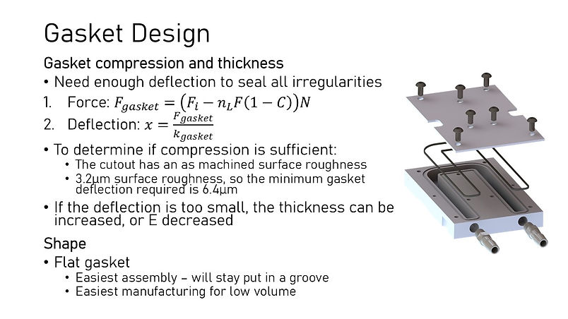
Gasket Design

Exterior Improvements
Traction Inverter + Cold Plate
2023 - 2024